In this tutorial I would like to show you how to configure the autopilot on your Honeycomb Bravo Quadrant Throttle for FlyByWire’s A32NX so that the LED lights, buttons and inputs work correctly. For the following setup you need the following:
- The Microsoft Flight Simulator 2020 (subject to a fee), can be purchased e.g. at Amazon
- A Honeycomb Bravo Throttle Quadrant (subject to a fee), can be bought at Amazon
- FlyByWire A32NX (free), download FlyByWire Simulations
- Spad.Next (fee required), download/buyable from Spad.Next
- Better Bravo Lights (free), download via Flightsim.to or Github website
Content of tutorial
Specifically, for autopilot functionality on the FlyByWire A32NX for the Honeycomb Bravo Throttle Quadrant, let’s look at the following buttons, knobs, and selectors:
- Button 1 – HDG Mode – Heading
- Button 2 – NAV Mode – Navigation
- Button 3 – APR Mode – Approach
- Button 5 – ALT Mode – Altitude
- Button 6 – VS Mode – Vertical Speed
- Button 7 – IAS Mode – Indicated Airspeed
- Button 8 – Autopilot Mode
- Button 13 – INCR Knob- Clockwise
- Button 14 – DECR Knob – Anticlockwise
- Button 17 – IAS Selector – Indicated Airspeed
- Button 19 – HDG Selector – Heading
- Button 20 – VS Selector – Vertical Speed
- Button 21 – ALT Selector – Altitude
Not included are button 4 (REV) and button 18 (CRS selector), which I misused in another post for the A/THR or the AutoBreaks. More information on this in the article Honeycomb Bravo – FBW 32NX – AutoThrust (Button 4).
A prerequisite for this tutorial is also the correct installation of the software Spad.Next and Better Bravo Lights, otherwise a configuration will not be possible. More details can be found in the article Honeycomb Bravo Throttle Quadrant – Configuration A32NX FlyByWire >> Software.
Autopilot throttle quadrant configuration
This section is divided into three parts. The configuration of the selectors (the selection knob for ALT, VS, HDG, CRS and IAS), the configuration of the knob (INCR / DECR) as well as the configuration of the individual radio knobs (HDG, NAV, APR, etc.).
Configuration of selectors
The configuration of the selectors is very easy in this tutorial. You don’t have to do anything here. As soon as you turn the radio button, the respective button gets the parameter 1. Otherwise the parameter is 0. If the radio button is set to “ALT”, for example, button 21 has the parameter 1 and the other selector buttons have the parameter 0. This information is useful for the configuration of the knob in the next paragraph.
Configuration of the knob
The rotary knob can be moved in two directions. Clockwise and counterclockwise. But here we have to pay attention to several things. Firstly, we are only allowed to change the selected value, secondly, the values have different scales. HDG should go from about 0 to 359 while ALT should go from 0 to 40000. There are also subtleties, for example with ALT in the FBW A32NX you can choose whether you want to enter the height in 1000ft or 100ft increments. Of course, you also need the currently set value. In summary, there is a lot of logic behind this button.
For this reason, you need the Spad.Next program here, since the correct value can be determined and entered using conditions (e.g. the current selector and other LVARs from the simulator).
In the first step we will discuss Button 13 – INCR Knob- Clockwise, so you turn the knob in the right direction. This section is also divided into the individual selectors so that the configuration is clear and easy.
ALT / Altitude
For ALT we need 3 pieces of information in advance:
- Is the ALT selector selected (condition, hardware button)
- Should the value be increased by 100ft or 1000ft (condition, LVAR)
- What is the currently set value ALT value (local variable, LVAR)
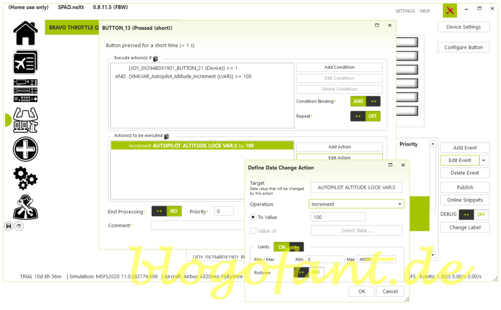
For this reason, to configure the height, we need two actions with two conditions each (selector and increment value). You can see how the reading of values works in the article on the Read Spad.Next variables.
; ALT increment value
XMLVAR_AUTOPILOT_ALTITUDE_INCREMENT = 100/1000
; Actual ALT value
AUTOPILOT ALTITUDE LOCK VAR:3 = ?? ft
; Selector Value
Button 21 = 1
The first action is that the selector is set to ALT (button 21 = 1) and the change value is 100ft. Then we just have to increase the current value by 100 (AUTOPILOT ALTITUDE LOCK VAR:3 = AUTOPILOT ALTITUDE LOCK VAR:3 + 100ft). It must be noted that a limit should be set (e.g. between 0 and 40000ft).
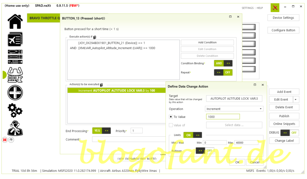
The second action is the same except that the change value is 1000ft. To do this, only the condition and the increment value must be adjusted. The height configuration is then complete.
VS / Vertical Speed
The next step is to define the vertical speed. This also requires values.
- Is the VS selector selected (condition, hardware button)
- Is the V/S / HDG or FPA / TRK mode activated (condition, LVAR)
- How is the currently set VS value (local variable, LVAR)
We can also use variables for this.
; Mode
A32NX_TRK_FPA_MODE_ACTIVE = 0 (HDG/VS)/ 1 (TRK/FPA)
; Actual VS value
A32NX_AUTOPILOT_VS_SELECTED = ?? ft
; Selector Value
Button 20 = 1
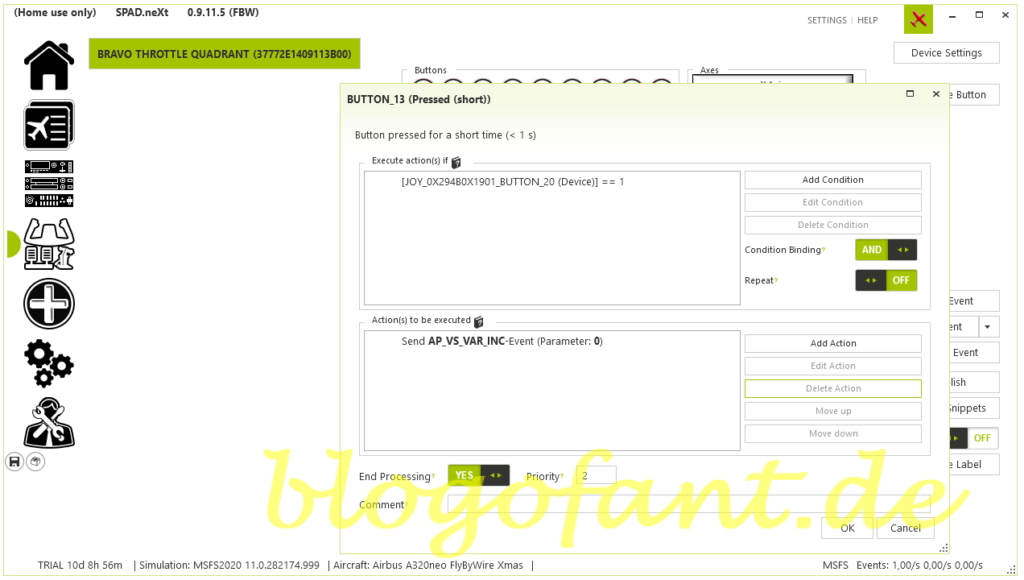
So the action is to check what value is set and then increase it. This value is changed using the A32NX.FCU_VS_INC command (alternatively: AP_VS_VAR_INC). The advantage of this: It doesn’t matter whether VS or FPA was selected, both work. In VS mode the value is increased by 100ft, in FPA mode by 0.1. This also allows the configuration to be kept minimalist.
HDG / Heading
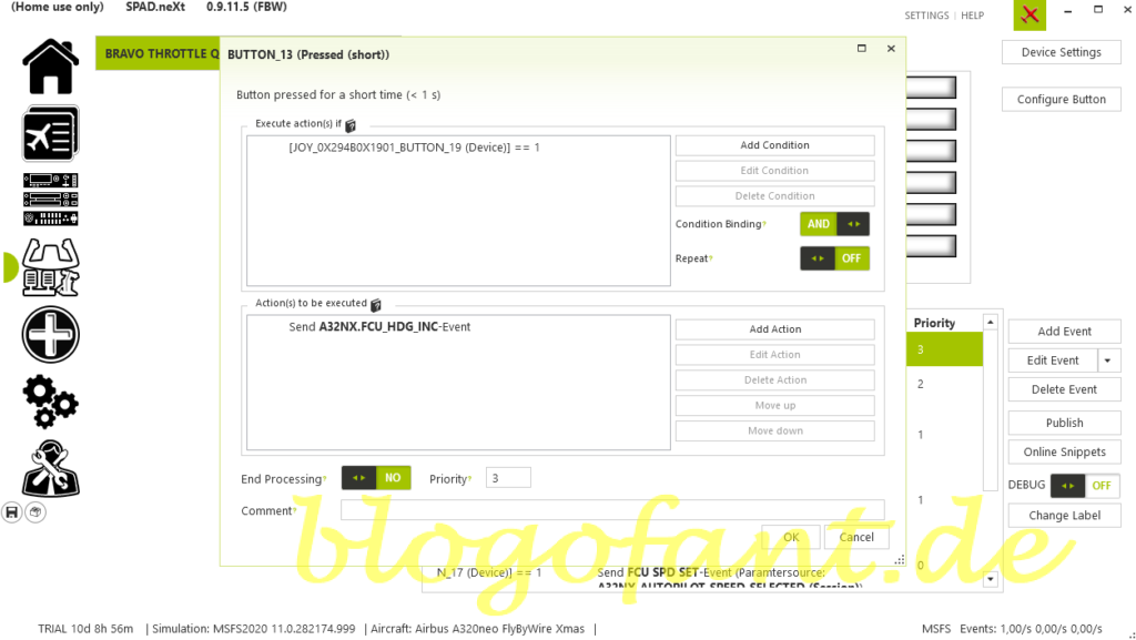
For heading, proceed in the same way as with V/S. Whether HDG or Track, both are covered with one configuration. It is important that button 19 = 1 (in HDG mode). The respective value is then increased via the event A32NX.FCU_HDG_INC.
IAS / Indicated Air Speed
The configuration is also the same for the IAS (whether in nodes or march). Button 17 = 1 must be activated (in IAS mode). The respective value is then increased via the A32NX.FCU_SPD_INC event.
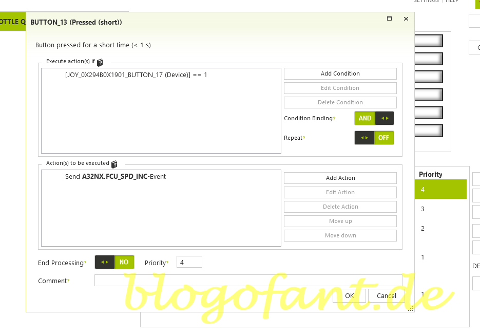
In the second step we will discuss Button 14 – DECR Knob-Anit-Clockwise, so you turn the knob in the left direction. This section is also divided into the individual selectors so that the configuration is clear and easy. However, I left out the descriptions here. If you are interested read the description clockwise. The whole setup is visible in the first picture.
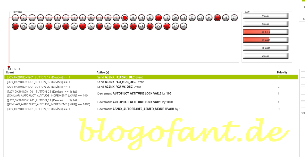
ALT
Reduce altitude by 100ft. The required event is AUTOPILOT ALTITUDE LOCK VAR:3 with the parameter Decrement 100.
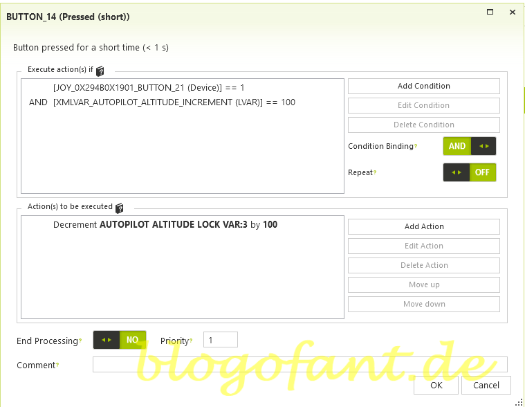
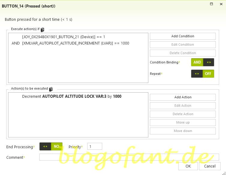
Reduce altitude by 1000ft. The required event is AUTOPILOT ALTITUDE LOCK VAR:3 with the parameter Decrement 1000.
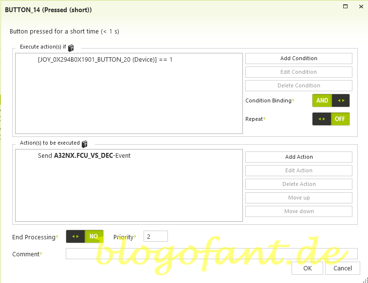
VS
Reduce vertical speed. The required event is A32NX.FCU_VS_DEC.
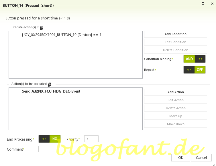
HDG
Reduce heading. The required event is A32NX.FCU_HDG_DEC.
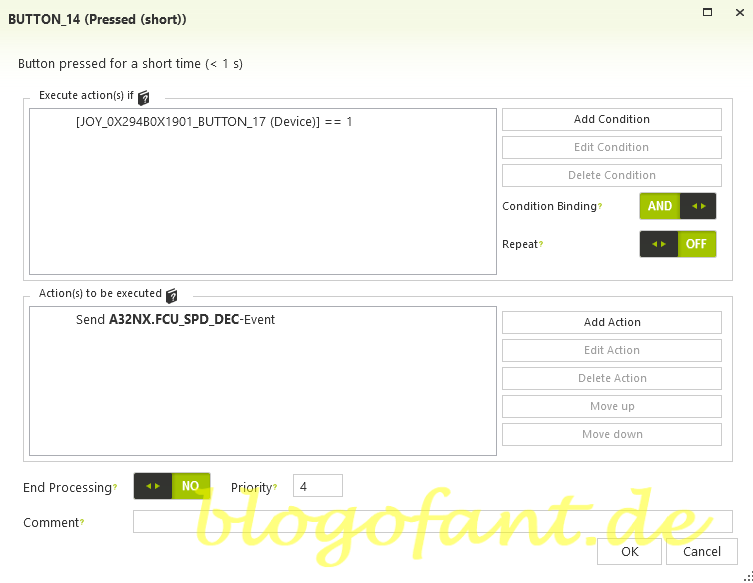
IAS
Reduce speed. The required event is A32NX.FCU_SPD_DEC.
Now the remaining selection buttons are set, with Airbus distinguishing between HDG and NAV. The buttons should also have special assignments, such as switching from nodes to March and vice versa and switching from HDG/VS to TRK/FPA and vice versa.
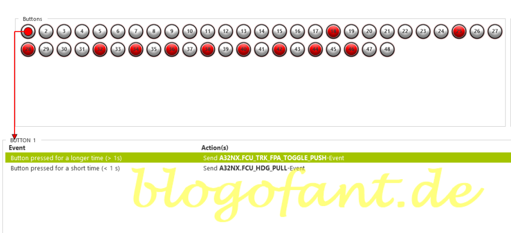
The FlyByWire A32NX splits the HDG mode into two options. Option 1 is to activate HDG mode, i.e. the option to fly in one direction. To do this, press the button briefly. The second option is to switch between HDG/VS and TRK/FPA. To do this, simply hold down the button for longer than a second.
The required events are:
- A32NX.FCU_HDG_PULL: to activate HDG mode
- A32NX.FCU_TRK_FPA_TOGGLE_PUSH: to switch modes between HDG/VS and TRK /FPA
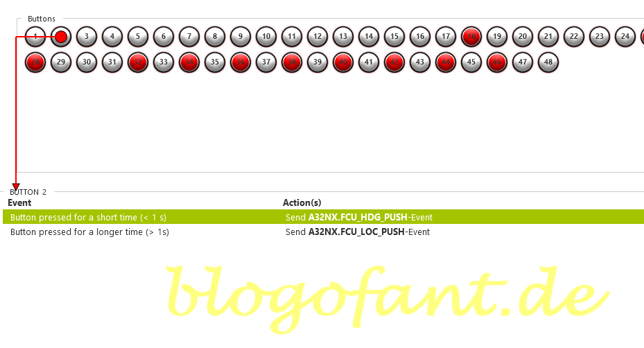
The NAV button is also used for two options. The first option with a short push on the button activates the NAV mode (and thus deactivates the HDG mode). Now the aircraft flies the route from the FlightPlan. The second option is to activate LOC mode by simply pressing the button for more than a second.
The required events are:
- A32NX.FCU_HDG_PUSH: to activate NAV mode
- A32NX.FCU_LOC_PUSH: to activate LOC mode
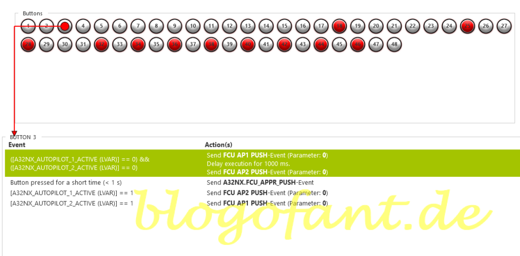
The approach mode should also offer two options. With a short push event, the APPR mode should be activated. Of course, this only works if the data entered in the FlightPlan allows it. On the other hand, the second autopilot (for a DUAL landing) is often activated during the approach. For this reason, a long press on the button should switch on the second autopilot. But there are three options here:
- first AP is active (condition) => the second autopilot must be activated
- second AP is active (condition) => the first autopilot must be activated
- no AP is active (condition => both autopilots must be activated
The necessary events are as follows:
- A32NX.FCU_APPR_PUSH: Activates APPR mode
- FCU AP1 PUSH: Activates autopilot 1
- FCU AP2 PUSH: Activates autopilot 2
- A32NX_AUTOPILOT_1_ACTIVE: LVAR of the first AP, with the parameter 0 (AP = OFF) and 1 (AP = ON)
- A32NX_AUTOPILOT_2_ACTIVE: LVAR of the second AP, with the parameter 0 (AP = OFF) and 1 (AP = ON)
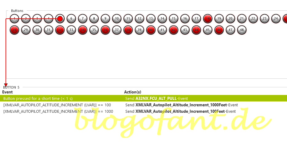
The ALT button should be used for two options. The first option is to transmit the set altitude to the autopilot. The A32NX.FCU_ALT_PULL event is required for this. The second option is to change the settings whether the altitude knob makes a change of 100ft or 1000ft. This is done with a long press on the button and the other condition.
The events are thus:
- A32NX.FCU_ALT_PULL: Activates the ALT mode
- XMLVAR_AUTOPILOT_ALTITUDE_INCREMENT: Returns 100 or 1000, depending on the parameter set
- XMLVAR_Autopilot_Altitude_Increment_100Feet: Altitude knob is set to 100ft change
- XMLVAR_Autopilot_Altitude_Increment_1000Feet: Altitude knob is set to 1000ft change
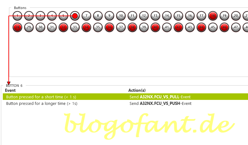
For Vertical Speed, it should simply implement the push event and pull event of the button.
The events are thus:
- A32NX.FCU_VS_PULL
- A32NX.FCU_VS_PUSH
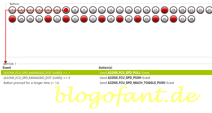
Three options should be set with the speed button. First, the speed should be managed, if a selected speed was previously set. As a second option, the speed should no longer be managed, but self-selected. The third option (long button click) is to switch between MACH and NODE.
The associated events are thus:
- A32NX.FCU_SPD_PULL: Pull event from IAS
- A32NX.FCU_SPD_PUSH: Push event from IAS
- A32NX_FCU_SPD_MANAGED_DOT: Parameters of 0 (set speed) or 1 (speed managed)
- A32NX.FCU_SPD_MACH_TOGGLE_PUSH: Toggle between knots and mach speed
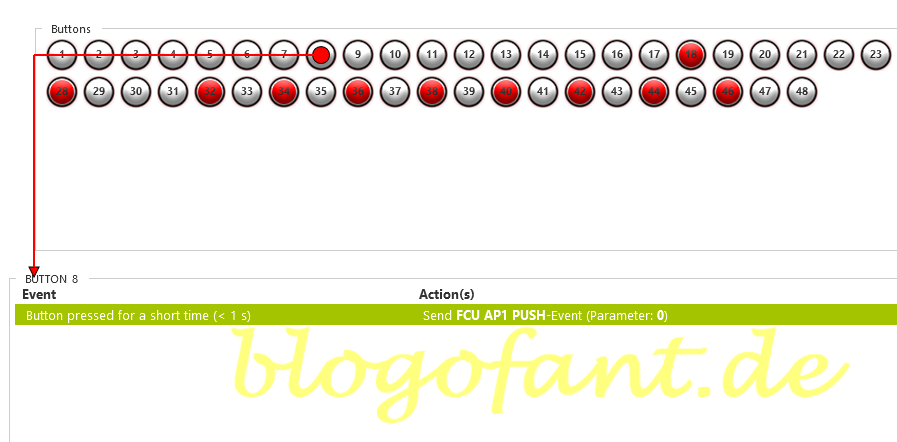
The autopilot button should be used to switch the autopilot on or off. With the A32NX, autopilot 1 is always addressed, so that it is always activated or deactivated. Anyone who flies the AP2 more often could add conditions to this event.
The associated event is:
- FCU AP1 Push: Enables / disables autopilot 1
Configure LED lights
In order for the LED lights to work properly, Better Bravo Lights software is required. After downloading the Better Bravo Light simply follow the installation instructions. Then in the community folder under BetterBravoLights (caution: do not use the folder Better-Bravo-Lights-LVAR-Module) a file called Config.ini. The LED lamps can now be adjusted here, in our case for the A32NX.
Now customize the config.ini file in the Community/Better Bravo Lights folder. You can find the complete file in the Download or view Post FBW A32XN Configuration. Otherwise add the following lines in the section of the FBW. The lines are self-explanatory with a few exceptions:
- NAV = L:A32NX_FCU_HDG_MANAGED_DOT == 1 (Managed (parameter = 1) means that the autopilot has taken over this)
- REV = L :A32NX_AUTOTHRUST_MODE != 0 (AutoThrust has a total of modes from 0 to 14, where 0 means off and any other mode means on)
; HDG
HDG = L:A32NX_FCU_HDG_MANAGED_DOT == 0
; NAV
NAV = L:A32NX_FCU_HDG_MANAGED_DOT == 1
; APR
; REV for Auto Thrust Mode
REV = L:A32NX_AUTOTHRUST_MODE != 0
; ALT
ALT = L:A32NX_FCU_ALT_MANAGED == 0
; VS
VS = L:A32NX_FCU_VS_MANAGED == 0
; IAS for Speed
IAS = L:A32NX_FCU_SPD_MANAGED_DOT == 0
More configurations
- Configure the autopilot
- Configuration for SeatBelts
- Configuration for AutoBrakes
- Configuration for the APU
- Configure A/THR
- Configure for taxi lights
- Configure for landing lights
- Configuring flaps & spoilers
- Configuration in MSFS
- To the overview page of the configuration of the A32NX
- Key Map / Button Map Honeycomb Bravo
More about the Honeycomb Bravo Throttle Quadrant
More about the Honeycomb Bravo Throttle Quadrant can be found on the Honeycomb Bravo Throttle Quadrant Overview Page, the Configuration page of the Honeycomb Bravo Throttle Quadrant for many other aircraft and the Honeycomb Bravo Throttle Quadrant Test and Recommendation.


1 thought on “Honeycomb Bravo – FBW 32NX – AutoPilot”
Comments are closed.